
Well. That was interesting…
If you read the last post you know that Cristi and I are whipping our new, used Casita Spirit Deluxe 17 into shape for a summer on the road. Electrical and battery problems have been an issue since we picked up the rig. A fresh battery seemed like the solution but further exploration in the guts of the trailer indicated that the converter was blown.

What’s a converter, you ask? A month ago I had no idea, but after some help from the community over at the Casita Forum I know a little more. The converter is something like an electrical nerve center for the whole camper. It charges the battery. It provides power to DC systems when you’re plugged into AC “shore power”. With a bad converter your battery will run dead and none of your DC systems will work. Hmmm…
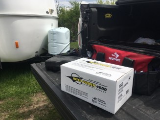
The solution to a bad converter is straightforward: put in a new one. The folks over at the forum recommended an upgrade to a Progressive Dynamics converter with a computerized smart charge system that varies the current to the battery depending on it’s charge status. I clicked the suggested link and ordered up a PD4635V from Best Converter in Enterprise, Alabama.
And then I started to second guess whether I bought the right thing. I spoke with a couple people who suggested upgrading to a more powerful version of the converter. This would allow me to charge a second battery should I choose to add one to the camper to improve boondocking performance. The next day I gave Randy a call at Best Converter and asked him to switch me over to the 45 amp version. He suggested I spend twenty bucks more and get the PD4645VL, which is the newest and most robust version of the converter. Done deal.
Somewhere along the line some wires got crossed (haha) and when I received my revised invoice it showed that I had been shipped a PD4635VL–the 35 amp version of the new converter–instead of the more powerful unit.
I only mention this because it gives me a chance to talk about how absolutely outstanding Randy and the crew at Best Converter are. I gave him a call and he shipped out a 4645 the same day along with a call tag to ship back the 4635 when it arrived. The second converter arrived a couple days after the first. I stuck the call tag on the 4635 and dropped it at the local FedEx store to be shipped back. The whole thing didn’t cost me a penny more and I still had the part in time to install it over the weekend. If you need a converter or any other RV parts these folks are the real deal. Sincere thanks!

Over at the Casita, I unboxed the new converter and read through the directions. I had been assured that the process of switching things over was straightforward. But, given the fact that I’m almost completely ignorant about electrical things I was pretty intimidated. When I was a kid, I took apart a fancy flashlight to fix it and never got it back together again. Looking at the shiny new converter and fuse board I had visions of a similar mistake turning this thing into a $200 brick.
So, with no small amount of anxiety, I waded in.

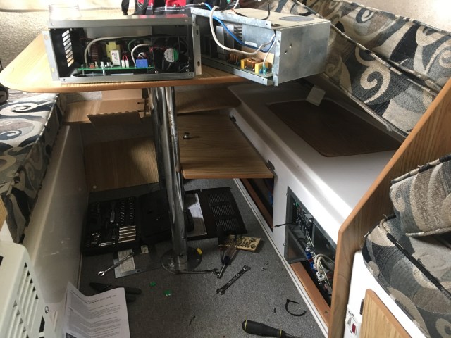
First step was to disconnect the battery. Next I removed the cover to the converter box. This revealed the old converter and a panel covering the AC side of the fuse box.

Removing the cover on the AC side exposes the neutral bus and ground bar along with the connections to the AC circuit breakers. I took a few minutes to cut back a scorched wire on the neutral bus and strip it down to clean copper. Once it was screwed back into the bus I dug into the next step.

The first real step in the process is to disconnect the the AC power to the old converter. This is followed up by disconnecting the DC fuse panel from the converter and from the battery leads.

At this point things got interesting. The instructions said that I was supposed to pull the battery leads off the old fuse board and attach them to the new fuse board. But I didn’t have nearly enough wire to make this happen. The old board had the wires attached toward the bottom edge, and the new board put them at the top. I didn’t have enough rope.

A fair amount of pulling, cursing and fuming followed from my prone position in front of the panel. After a few minutes I gave up on the battery leads and decided to start switching over the leads from the old fuse panel to the new. I would figure out the battery leads later.
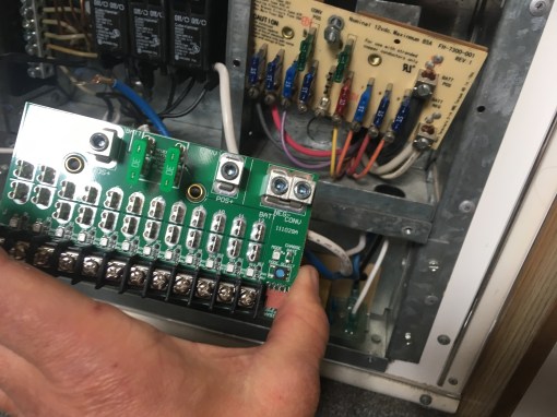

More hilarity followed as I discovered there wasn’t enough slack in the wires that fed into the old fuse board to allow them to be switched over to the new board one at a time. I would have to take them all off, remember the sequence and put them onto the new board in the correct order. I took a picture. And drew a diagram.
Once the wires were all shifted over and the fuses set in place I went back to the problem of the short battery leads. I pulled the old converter out of the box and discovered that all the DC wires were bundled tightly together and zip tied to the water line behind the converter. I cut the ties and was able to liberate enough slack to connect the fuse board to the positive and negative battery leads.

With the DC fuse board screwed into place I installed the new converter unit and attached the two DC wires to the fuse panel. Then I threaded the three AC wires into the AC side of the panel. I read the instructions again. They told me to connect the neutral lead to the neutral bus, the green ground wire to the ground bar, and the positive wire to the circuit breaker. The instructions also said something about “if your previous converter was installed with a utility pigtail you may make another utility pigtail from two lengths of XXX wire. Under no circumstances install two wires into the circuit breaker…” Oh boy.


Well, I can tell you, I don’t know what a utility pigtail is. I reckoned it was the Y shaped wire that was crimped together on the old converter. This was attached to a couple positive wires on the AC side and plugged into the circuit breaker. I didn’t have any spare wire, so I clipped the “pigtail” off the old converter and connected it to the two positive wires and the new converter lead with a couple wire nuts. Then I plugged the crimped junction into the circuit breaker and hoped for the best.
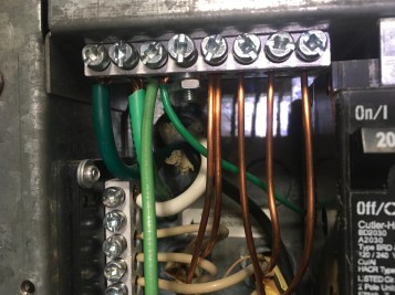
The next puzzle was the ground wire. The old converter didn’t have a ground. Maybe that’s why it was blown up. The new one had a ground wire, but I didn’t have any open slots in the ground bar. If I knew anything about electricity I would have known if it was OK to double up ground wires in the bar. Of course, I didn’t know that, but I doubled them up anyway and hoped for the best. Didn’t seem like there was any other way to do it.
The final step of the install was to connect the digital hardware on the DC panel to the converter using a long 4 pin connecting wire and replace all the covers. This complete I went outside, reconnected the battery, and waited to hear a loud “POP!” Nothing. I connected the trailer to the truck, turned the key and climbed back inside to see if the battery was charging.

Back inside the green light was on in the converter and everything seemed AOK. I plugged my charge meter into the DC outlet in the ceiling and saw the battery charge climb from 12.08 volts up to 12.14. I ran the truck for a few minutes and watched the meter to see if the alternator was putting out enough juice to charge the battery fully. The meter held steady at 12.14. The real test would come when I plugged it into AC power.
I didn’t have any AC at the storage unit, so I drove the Casita home to our apartment where I could sling a 50 foot extension cord off our second story balcony. I plugged in the shore power cord and crossed my fingers.
Back inside the Casita, the converter was charging like a demon. My battery charge meter showed it charging at above 14 volts. I pushed the manual override button to select power boost mode and headed inside for a beer.
Forty five minutes later I had a full charge on the battery. Outstanding.
That evening I posted up a few pictures and questions to the Casita Forum and got the thumbs up on my choices about the ground wire and utility pigtail. Install is good to go.
So there you have it. Switching over the power converter in your Casita is a pretty straightforward process after all.
The converter was the biggest and most expensive challenge that we’ve had to face in getting our Casita ready for a summer on the road. With this task behind us we’re rapidly coming to the end of the critical systems that need to be repaired or upgraded. Now we’re on to cosmetics, customization and making the trailer into a cozy home on the road.
If you enjoyed this post, please consider subscribing to our blog by using one of the links in the menu on the right side of the screen. On your mobile device you’ll find the links if you scroll to the bottom of the post. Thanks!

Nice job! That shit is intimidating.
Thanks Mike! Would have been a fun project to tackle with you and a dozen coldbeers!
Shocking! Way to Go!
Nice job !👍 and thanks for the documentation ……I know some day I will have to change ours out..
Thanks Dan.
I know this may sound naive but how did you remove the cover for the converter (what tool(s) did you use)? Those type of screws/rivets are new to me.
And thank you for the detailed installation instructions for the new converter. I will be attempting this soon!
Hi Sheri,
I think the screws were all pretty straightforward. Phillips on the outside of the cabinet and some hex/standard machine screws on the inside. I don’t think they’ll give you any trouble.
That said, I have a little hand-held screwdriver that takes interchangeable bits. Mine came with all kinds of bits: hex, square, phillips, common, etc. Might be worth picking something like that up for your tool kit. They’re really handy.
One thing I didn’t mention in the post that has come up. The screws provided to hold the converter into the cabinet seem to be just a little too small. They work loose over time. Next time I tighten them I’m going to use some blue Loctite on the threads. If that doesn’t work I’ll get some new machine screws or sheet metal screws and replace them.
Good luck with your project!
You didn’t think of trying fitting a dollar’s worth of capacitor and a minute with a soldering iron first?
A blown capacitor is very common and I must have changed hundreds over the years.
I did. Discussed it with some friends who work on stereo equipment. Decided that the improved performance of an upgraded converter was worth spending a little money on.
Thank you very much for your write-up! I did this swap to two of our trailers, a Casita and an older toy-hauler. Yours is the best written (funny!) that I found anywhere. Thank you!
Thanks Russ!
What year Casita is this?
2008
Hi, I am looking to pull the cover holding the electric panel and covering battery and hot water heater. Obviously I would disconnect all power. It appears the box is screwed and riveted in. How would you go about removing this cover. Trailer was damaged in rear which has led to the need to stop leaks and build up the back with epoxy and glass. Only way is to pull cabinet. One guy suggested cutting the cover to the left of the panel and converter and unscrewing those screws holding that part of the panel. It would work I guess, but would require patching up the panel on reassembly with some bolts or rivets. Thanks for any suggestions
Hey Mark,
We no longer have our Casita so I cant check for certain, but I believe the fiberglass bench/cabinet is screwed into place in a similar way to the side benches for the dinette that I removed in the “ooh that smell” post. Should be able to remove the whole thing as a unit if you track down all the fasteners.
Your article is exactly what I have been looking for….a basic description on replacing your converter! We just bought a 2005 SD and I really have been having difficulties understanding the advanced descriptions etc. of those members of the Casita Forum and their terminology. Your images are so beneficial to me who also has limited knowledge of electrical work/repairs. Thanks so much !
That’s great! I’m glad the article helped! Thanks for the kind words.
This article is just perfect for me ! Limited electrical knowledge, but your explanations re. your Casita are invaluable….we just bought. 2005 SD with many mods done by LHOTR but I know down the road that I might have to replace the converter.
Thanks for posting !